
There are 7 photos and one sketch on this page. Please make sure you scroll all the way down so that you can see and read everything.
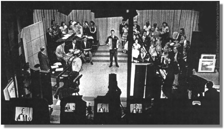
The Children's Hour
Studio A
1948
This picture is looking out of the control room (Control Room A) and into the studio which did not have an audience.
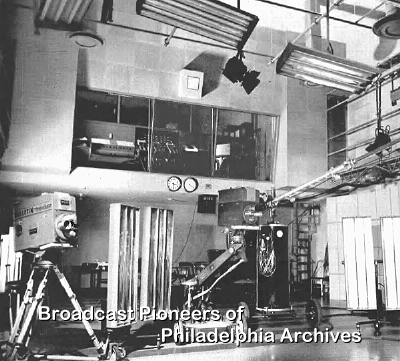
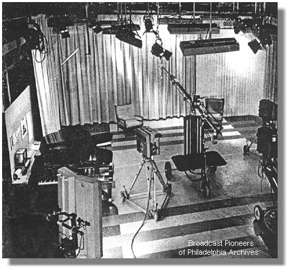
Studio A & Control Room A
1948
This view of WCAU-TV's Studio A shows the elevated position of the control room. Space under control was available for camera maneuvering or for storage of scenery, props and other items.
(Click on the photo to see a larger version of the area)
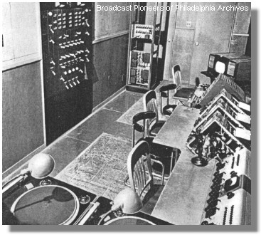
Control Room A
1948
Broadcast Pioneers member Charlie Higgins e-mails: "...If you're interested, the "Off Air Monitor" shown in the pix (upper right) and on the floor plan was an RCA TS 630 receiver. I had one of these sets. It was one of the best TV sets ever made by RCA."
Turntables and audio consolette are shown in the foreground. Video units, just beyond, included three field type camera control units and a studio-type mixer and master monitor unit. Panel on the wall at the rear was a lighting control center.
(Click on the above photo to see a closeup)
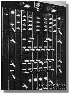
Closeup of the Lighting Panel
Control Room A
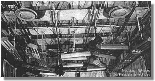
Studio A
1948
Foundation lighting in WCAU-TV studios was obtained with specially designed fluorescent fixtures each of which contained three 40 watt 3500 degree standard fluorescent lamps. All fixtures could have been rotated in any direction and adjusted as to height.
(Click on the photo to see the complete studio)
Studio A
1948
Front lighting in WCAU-TV studios was supplied by adjustable fluorescent units similar to those mounted overhead.
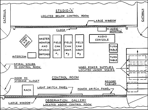
Floor Plan on Control Room A
1948
This shows location of equipment units. The observation gallery, which was a half floor above the control room, provided a view through the control room and into the studio.
WCAU-TV decided to equip all of their studios and control rooms with field type gear so that remote and studio equipment would be interchangeable. Nine RCA TK-30A camera chains were used among the three TV studios, any of which could have been moved to remote pickup sites if required. A studio type switcher, an RCA TS-10A, was used in both Control Room A & B.
Placement of equipment was essentially the same in all of the studio control rooms. In Control Room A, there were three camera control units which were mounted adjacent to and near the middle of the large window which separated the studio from the control room. Immediately to the left of the camera control units were located the studio type switcher and master monitor. To the left of the producer, an RCA TS 630 receiver served as an off-the-air monitor. To the right of the camera control units, the audio consolette was mounted on a specially built wooden stand. Two turntables were placed to the right of the audio consolette within easy reach of the audio engineer.
This arrangement of the video and audio equipment provided the producer, video control and audio operators with a full view of the studio as well as a view of the pictures on the camera controls, master monitor and on-the-air receiver.
A Tele-talk unit was mounted to the producer's left, between his master monitor and air monitor, with which he could communicate directly with the TV control room, Studio B, Studio X or the projection room. A talk-back microphone was located on the producer's right with which he was able to talk to the studio during rehearsals. The power supplies for the three camera chains were located to the far right underneath the steps leading out of the control room. The power supplies for the switcher and master monitor and the stabilizing amplifier were rack mounted near the left rear corner of the control room.
Wiring ducts covered by aluminum plates ran the length of the control room front and back, with a connecting wire duct in the middle and at the right end of the control room for housing of all inter-connecting cables and wires. Camera cables were running from the floor along the lighting bridge to the three cameras. The control panel for Studio A's lighting equipment was located centrally on the rear wall of the control room. A door on the left of the control room provided access to a steel spiral stairway which led to Studio B and to the TV control room and projection room one floor below Studio A and B.
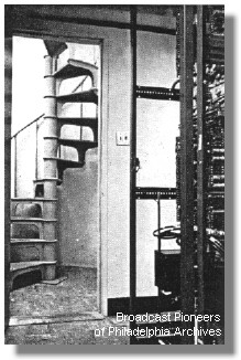
Spiral Staircase
leads to Studio B & TV Control
1948
On both right and left front corners of the control room there were doors leading to the studio lighting bridge. An equipment locker was situated at the far left rear corner of the control room.
Above the level of the lighting panel board at the rear of the control room, a long window separated the control room from the gallery, a space from which spectators were able to see both into the control room and into the studio.
From the official archives of the Broadcast Pioneers of Philadelphia
Photos originally donated by Broadcast Pioneers member Allen Murphy
All Rights Reserved

The e-mail address of the Broadcast Pioneers of Philadelphia is pioneers@broadcastpioneers.com